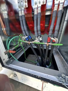
Medium Voltage Electrical Services
How Medium Voltage Cable Fault Location Works: Methods, Equipment & Repair
Medium-voltage electrical systems are an essential part of many commercial and industrial facilities. Manufacturing plants, distribution centers, hospitals, educational campuses, agricultural operations, water treatment facilities, and large commercial properties may depend on medium-voltage cables to distribute electrical power between switchgear, transformers, and other critical equipment.
When one of these cables develops a fault, the consequences can be significant.
A failed underground feeder can interrupt production, shut down equipment, disrupt building operations, and create expensive downtime. Unlike a damaged overhead cable or a visibly failed electrical component, an underground cable fault may be hidden beneath pavement, landscaping, concrete, or several feet of soil.
Finding the exact location of the fault is often one of the most challenging parts of restoring the electrical system.
Specialized medium-voltage cable fault-location methods allow qualified electrical professionals to investigate cable failures, estimate the distance to a fault, and pinpoint damaged sections before planning repairs.
In this guide, we'll explain how medium-voltage cable fault location works, what causes cable failures, the equipment used to locate underground faults, and what happens after a damaged cable is identified.
What Is a Medium Voltage Cable Fault?
A medium-voltage cable fault occurs when a cable or associated accessory develops an electrical defect that interferes with its intended operation.
Medium-voltage cable systems commonly use voltage classes such as 5 kV, 15 kV, 25 kV, and 35 kV. These cables are designed with specialized insulation, shielding, and protective components to withstand the electrical stresses associated with higher-voltage power distribution.
A fault can occur in the cable itself, at a splice, at a termination, or within another associated component.
Depending on the nature of the failure, the result may be an electrical short circuit, ground fault, open conductor, insulation breakdown, or intermittent electrical problem.
Common Types of Medium Voltage Cable Faults
Phase-to-Ground Faults
An unintended electrical path develops between an energized conductor and ground or grounded components. Damaged insulation, moisture-related deterioration, or physical damage may contribute.
Phase-to-Phase Faults
An unintended electrical connection develops between two phase conductors. Available fault current depends on the electrical system configuration.
Open-Conductor Faults
The electrical path through a conductor or connection becomes interrupted. Causes can include mechanical damage or failed connections.
High-Resistance Faults
Some faults have relatively high electrical resistance instead of behaving like direct short circuits. These may be difficult to identify using certain conventional locating methods.
Intermittent Faults
Problems appear only under certain conditions, potentially influenced by temperature, moisture, electrical loading, or other operating factors.
Key takeaway: Different cable faults behave differently. The locating method must be appropriate for the cable system and the electrical characteristics of the fault.
What Causes Medium Voltage Cable Faults?
Medium-voltage cables are engineered for demanding electrical environments, but they are not immune to damage or deterioration.
1. Insulation Deterioration
Cable insulation is designed to withstand electrical stress over its intended service life. Over time, electrical, thermal, environmental, and mechanical stresses can contribute to insulation degradation.
The condition of the insulation depends on cable construction, operating conditions, installation quality, and environmental exposure. Some defects develop gradually before eventual failure.
2. Moisture Intrusion and Water-Related Damage
Underground cables may encounter wet soil, groundwater, flooded vaults, and other moisture-related conditions.
Damaged jackets, compromised accessories, or other defects can create opportunities for moisture-related deterioration. Certain polymeric insulation systems may experience water-treeing under applicable conditions.
3. Excavation and Construction Damage
Underground electrical cables can be damaged during:
- Excavation and trenching
- Underground utility installation
- Drilling and boring
- Roadway or parking lot construction
- Landscaping and grading
- Other activities involving buried infrastructure
Physical damage may cause immediate failure or weaken the cable and contribute to problems later.
Before excavation, applicable utility-notification requirements and site-specific procedures must be followed. USA North 811 provides information about the utility notification process in its service territory. Privately owned electrical infrastructure may require separate locating arrangements.
4. Failed Cable Splices and Terminations
A medium-voltage cable splice is more than a connection between two conductors.
Depending on the system, it must restore electrical continuity, insulation, stress control, shielding, grounding continuity, and environmental protection.
Improper installation, contamination, incompatible components, moisture intrusion, or physical deterioration can compromise a splice.
Similarly, cable terminations may develop problems when components deteriorate or are improperly installed.
Related reading: What Is Medium Voltage Splicing and Why Is It So Critical?
5. Mechanical Stress and Physical Damage
Excessive bending, pulling damage, movement, crushing forces, and other mechanical conditions may affect cable integrity.
Damage to the insulation or shielding can create conditions that eventually lead to electrical failure.
6. Installation or Manufacturing Defects
Although modern medium-voltage cable systems are manufactured to demanding specifications, defects can occur.
Problems may also result from improper installation, unsuitable accessories, or failure to follow manufacturer requirements.
Not every cable failure indicates poor workmanship. Determining the cause requires evaluation of the actual system.
How Does Medium Voltage Cable Fault Location Work?
Medium-voltage cable fault location is a specialized diagnostic process used to determine where a cable has failed.
The process involves more than applying a test instrument. Qualified technicians must understand the electrical system, cable construction, and nature of the problem.
Typical Cable Fault-Location Workflow
Conceptual workflow only. Actual procedures depend on the electrical system, fault characteristics, and applicable safety requirements.
Step 1: Initial System Assessment
Before fault-location work begins, the system must be assessed by qualified personnel.
Relevant information may include cable voltage class, construction, approximate length, route, existing splices, terminations, operating history, and protective-device indications.
Drawings and maintenance records can help establish the cable route and connected equipment.
Because medium-voltage systems present serious hazards, affected equipment must be managed under appropriate electrical safety and hazardous-energy-control procedures.
Step 2: Fault Characterization
The next objective is to understand the nature of the fault.
A low-resistance fault may be easier to identify using certain reflectometry techniques than a high-resistance or intermittent fault.
Understanding these characteristics helps qualified technicians select suitable diagnostic and locating methods.
Step 3: Fault Prelocation
Prelocation estimates the distance to the fault along the cable.
Specialized instruments help determine whether the fault is relatively close to the testing location or farther along the cable route.
Distance along the cable is not necessarily the same as straight-line distance across the ground.
A cable may follow bends, duct banks, vaults, and other underground pathways.
Step 4: Precise Fault Pinpointing
After the approximate distance is known, technicians may use suitable field-locating methods to narrow down the physical location.
Depending on the fault and cable configuration, these methods can involve acoustic, electromagnetic, or combined detection techniques.
The objective is to support accurate repair planning and avoid unnecessary excavation.
Step 5: Repair Evaluation
Once the location is identified, the affected cable section can be evaluated.
The appropriate solution may involve localized repair, an engineered splice, partial cable replacement, or replacement of a larger section.
Step 6: Testing and Return to Service
Following repair, the system may require inspection, acceptance testing, or diagnostic testing according to project requirements and applicable standards.
The objective is to verify that the repair is suitable before returning the cable to normal operation.
Common Medium Voltage Cable Fault Location Methods
Several technologies are used to investigate and locate medium-voltage cable faults.
No single method is ideal for every situation. Selection depends on the fault type, cable construction, system condition, and available information.
Time Domain Reflectometry (TDR)
Time Domain Reflectometry (TDR) is a widely used technique for identifying changes in cable impedance.
A TDR instrument sends a low-energy electrical pulse into a cable and analyzes reflections produced by impedance changes.
These reflections can help identify discontinuities such as certain open circuits, short circuits, connections, or other changes along the cable.
How TDR Works — Conceptual Illustration
Simplified illustration. Not every cable fault produces a readily identifiable TDR reflection.
What Can TDR Help Identify?
TDR can help estimate the distance to certain faults or discontinuities and provide information about cable characteristics.
Its usefulness depends on the fault's electrical behavior.
A high-resistance fault may not produce a sufficiently distinct reflection to be located using conventional TDR alone. Other methods may be needed.
Arc Reflection Method (ARM)
The Arc Reflection Method (ARM) combines reflectometry with a specialized surge source to help locate certain faults that may not be clearly visible using conventional TDR.
The technique helps reveal the location of some high-resistance faults by creating a temporary condition that can be analyzed through reflectometry.
Arc reflection can be useful in appropriate underground cable fault-location applications.
However, it requires specialized equipment and qualified personnel. The method must be selected with consideration for cable condition, equipment limitations, and the potential consequences of applying high-voltage test energy.
Surge Generators
Specialized surge generators are used in certain cable fault-location methods.
These instruments can support fault prelocation and acoustic pinpointing where appropriate.
In some applications, the fault event produces a detectable acoustic signal that helps identify the damaged location.
High-Voltage Testing Requires Specialized Expertise
Surge-based methods are not suitable for every cable system or fault condition. They can impose substantial electrical stress and must be applied only by qualified personnel using procedures appropriate to the cable and equipment.
Acoustic Fault Pinpointing
Acoustic fault-location methods use sound associated with a fault event to help identify its physical location.
Specialized listening equipment can help technicians narrow down where the sound originates.
These methods can be useful for certain underground cable faults, although effectiveness depends on fault characteristics, cable depth, surrounding materials, and environmental noise.
Electromagnetic and Acoustic-Electromagnetic Pinpointing
Some fault-location systems combine acoustic detection with electromagnetic information.
The combination can help distinguish the fault location from nearby signals or environmental noise in suitable applications.
These methods may be useful when technicians have already estimated the fault distance and need to determine the physical location before excavation.
Cable Route Tracing
Cable route tracing is related to fault location, but it serves a different purpose.
Route tracing helps identify where a cable travels through a property or underground distribution system.
Fault location attempts to identify where that cable has electrically failed.
Example: Knowing that a fault is approximately 400 feet along a cable does not identify the correct excavation location unless the actual cable route is understood.
What Equipment Is Used for Medium Voltage Cable Fault Location?
Qualified electrical contractors may use several types of specialized instruments when investigating medium-voltage cable problems.
| Equipment | General Purpose |
|---|---|
| Time Domain Reflectometer (TDR) | Identifies reflections from cable impedance changes and helps estimate distance. |
| Cable Fault Prelocator | Estimates electrical distance to a fault using applicable methods. |
| Surge Generator | Supports certain high-voltage fault-location techniques. |
| Acoustic Pinpointing Equipment | Helps locate suitable underground faults through sound detection. |
| Electromagnetic Locator | Supports cable route tracing or compatible fault-location techniques. |
| Cable Diagnostic Equipment | Evaluates selected insulation or cable characteristics. |
Manufacturers such as Megger and BAUR publish technical information about cable fault-location equipment and methods.
Equipment selection depends on the system, nature of the fault, and applicable safety requirements.
Having sophisticated equipment does not eliminate the need for experience and technical judgment.
Underground Medium Voltage Cable Fault Location: Why Is It So Challenging?
Underground electrical distribution offers practical advantages, including protection from some forms of weather exposure and reduced visual impact.
However, underground installation also makes faults more difficult to access.
Long Underground Cable Runs
Commercial and industrial feeders may extend across large properties or between multiple buildings.
A fault can occur anywhere along the route, including beneath parking lots, landscaped areas, roadways, or structures.
Inaccurate or Missing Cable Drawings
Older facilities may have electrical systems that have been modified over many years.
If underground routes were not documented accurately, identifying the actual cable pathway can require additional investigation.
Multiple Cable Splices
A cable run may contain one or more splices.
These connections must be considered when evaluating cable condition and interpreting certain diagnostic results.
A splice is not automatically the cause of a fault, but it is part of the cable system that may need evaluation.
Underground Vaults and Duct Banks
Cables installed in conduits, duct banks, manholes, or underground vaults can present accessibility challenges.
The physical location of a fault may affect the feasibility and cost of repair.
Multiple Cables in the Same Area
Large facilities may have several feeders running through the same underground corridor.
Correctly identifying the affected cable is essential before repair work proceeds.
Misidentification can create severe safety hazards and unnecessary disruption.
What Happens After a Medium Voltage Cable Fault Is Located?
Locating the fault is an important milestone, but it does not automatically determine the appropriate repair.
The damaged cable must still be evaluated.
Evaluating the Extent of Damage
Once the faulted section is accessible, qualified personnel can assess the visible condition of the cable and determine what additional evaluation is necessary.
The damage may be localized, or it may indicate broader deterioration.
Medium Voltage Cable Splice Repair
In suitable circumstances, a damaged cable section can be removed and the remaining cable sections joined using an appropriately engineered medium-voltage splice.
The splice must be compatible with the cable construction, conductor, voltage class, insulation system, and installation environment.
It must also restore the required electrical and physical functions of the cable system.
Related article: What Is Medium Voltage Splicing and Why Is It So Critical?
Replacing a Damaged Cable Section
If damage is too extensive for localized repair, replacing a section of cable may be appropriate.
This approach may require new cable, compatible accessories, and additional installation work.
When Full Cable Replacement May Be Necessary
In some cases, the overall cable condition may make replacement a better option than repeated repairs.
Factors can include extensive insulation deterioration, multiple failures, widespread physical damage, cable age and condition, accessibility, and long-term system requirements.
The decision should be based on engineering and condition assessment rather than simply the presence of one fault.
Post-Repair Testing
Following repair or replacement, appropriate verification is an important part of returning the cable to service.
Testing requirements vary according to cable construction, insulation type, age, condition, project specifications, and applicable standards.
IEEE 400-series documents address field testing and evaluation of shielded power cable systems, with different guidance applicable to different testing methods.
The correct method must be selected for the particular cable system.
Can Medium Voltage Cable Faults Be Prevented?
Not every cable failure can be predicted or prevented.
Excavation accidents, unexpected physical damage, and certain equipment failures can occur even in well-maintained facilities.
However, proactive maintenance and condition assessment can help identify some developing problems and reduce avoidable risks.
Electrical System Inspections
Periodic inspections of accessible cable accessories, terminations, switchgear connections, and related components can help identify visible deterioration or environmental concerns.
Proper Cable Installation
Following manufacturer requirements and applicable standards during installation helps reduce avoidable problems involving cable handling, bending, pulling, splicing, and termination.
Moisture Management
Managing water intrusion in vaults, enclosures, and other electrical spaces can help protect equipment and accessories.
Cable Condition Assessment
Depending on the system, diagnostic techniques may be used to evaluate aspects of cable insulation condition.
- Very Low Frequency (VLF) testing
- Tan delta testing
- Partial discharge diagnostics
- Other applicable cable condition-assessment methods
Each method provides different information, and not all methods are appropriate for every cable system.
Maintenance Documentation
Accurate cable route drawings, splice records, test results, and maintenance history can make future troubleshooting more efficient.
A documented history can also help identify recurring problems or areas that deserve closer evaluation.
The National Fire Protection Association publishes NFPA 70B, which addresses electrical equipment maintenance, while the InterNational Electrical Testing Association publishes electrical testing standards used in the industry.
When Should a Facility Call a Medium Voltage Electrical Contractor?
Medium-voltage electrical problems should be evaluated by appropriately qualified professionals.
Situations that may require specialized attention include:
- Repeated medium-voltage feeder trips
- Unexplained loss of power to distribution equipment
- Suspected underground cable damage
- Failed cable accessories
- Abnormal diagnostic results
- Planned changes to medium-voltage distribution infrastructure
The appropriate response depends on the nature of the problem and the electrical system involved.
A repeated feeder trip does not necessarily prove that the underground cable has failed. Protective devices may operate because of faults or problems elsewhere in the system.
A qualified evaluation is necessary to identify the cause.
Why Specialized Experience Matters
Medium-voltage cable systems differ significantly from ordinary low-voltage electrical installations.
The work may involve specialized cable constructions, electrical stress-control systems, high-energy equipment, complex distribution arrangements, and significant safety hazards.
Electrical fault-location equipment also requires correct interpretation of results.
A distance estimate is not always the physical location of the fault, and an abnormal test result does not automatically identify the damaged component.
The combination of appropriate equipment, system knowledge, safety procedures, and technical judgment is essential.
Important Electrical Safety Notice
Medium-voltage equipment and fault-location testing present severe shock, arc-flash, and other electrical hazards.
Do not approach damaged electrical equipment, open medium-voltage enclosures, or attempt fault-location testing without appropriate qualifications and authorization.
Faulted equipment must be managed using applicable electrical safety and hazardous-energy-control procedures.
For further guidance, see OSHA Electrical Safety.
Medium Voltage Cable Fault Location Services in Stockton & Northern California
Commercial and industrial electrical systems require dependable power distribution.
When an underground feeder or medium-voltage cable develops a fault, accurately identifying the problem can be an important step toward restoring operations.
ASAP Electric provides specialized electrical services involving medium-voltage systems, electrical testing, and cable-fault work.
For facilities in Stockton and surrounding Northern California communities, understanding the cause and location of a cable fault can help determine whether the appropriate solution involves a cable splice, section replacement, additional testing, or broader system repairs.
Need Help With a Medium Voltage Cable Fault?
A damaged underground feeder or industrial cable system can disrupt critical operations.
Contact ASAP Electric to discuss your medium-voltage electrical system and the next steps for evaluating the problem.
Contact ASAP ElectricFrequently Asked Questions About Medium Voltage Cable Fault Location
What is medium voltage cable fault location?
Medium-voltage cable fault location is the process of identifying where a cable or associated accessory has developed an electrical failure. Qualified technicians use system information, diagnostic equipment, prelocation methods, and suitable pinpointing techniques to determine the fault location.
How do electricians locate faults in underground cables?
Qualified electrical professionals may use TDR, arc reflection, specialized surge equipment, cable route tracing, and acoustic or electromagnetic pinpointing methods. The appropriate approach depends on the cable system and fault characteristics.
What is TDR cable fault testing?
Time Domain Reflectometry uses electrical pulses and their reflections to identify changes in cable impedance. These reflections can help estimate the distance to certain faults or discontinuities along a cable.
Can a cable fault be located without digging up the entire cable?
Often, yes. Specialized fault-location methods can help narrow down the damaged area before excavation. However, accuracy and effectiveness depend on cable configuration, fault characteristics, and site conditions.
What causes underground medium voltage cables to fail?
Possible causes include insulation deterioration, moisture-related damage, excavation accidents, mechanical stress, damaged splices or terminations, and other electrical or environmental conditions.
Can a damaged medium voltage cable be spliced?
In some cases. A localized damaged section may be repairable using an engineered medium-voltage splice, provided the surrounding cable is suitable and the repair meets applicable system requirements. More extensive damage may require cable replacement.
How long does medium voltage cable fault location take?
There is no universal timeframe. Fault-location work varies depending on cable length, fault characteristics, accessibility, documentation, equipment availability, and site conditions. Some faults can be located relatively quickly, while complex underground systems may require extensive investigation.
Should a medium voltage cable be tested after repair?
Appropriate verification is generally an important part of returning a repaired cable system to service. Testing requirements and methods depend on cable construction, condition, project specifications, and applicable standards.
Conclusion: Accurate Fault Location Supports Better Repairs
Medium-voltage cable failures can create serious operational challenges for commercial and industrial facilities.
When the affected cable is buried underground, the problem becomes more complicated because the damaged section may not be visible or readily accessible.
Specialized fault-location technologies—including TDR, arc reflection, surge-based methods, acoustic pinpointing, and cable route tracing—can help qualified electrical professionals investigate and locate faults.
But the process doesn't end when the fault is found.
The damaged cable must still be evaluated, an appropriate repair or replacement strategy selected, and the completed work verified before the system returns to service.
Accurate fault location helps reduce uncertainty, supports better repair decisions, and contributes to the long-term reliability of medium-voltage electrical distribution systems.
For facility managers, maintenance supervisors, and commercial property owners, understanding these fundamentals can make it easier to plan repairs, communicate with electrical contractors, and evaluate recommendations when a cable failure occurs.
Authoritative Sources & Further Reading
- Megger — Electrical testing, cable fault location, reflectometry, and diagnostic equipment.
Megger Technical Resources - BAUR — Cable fault prelocation, pinpointing, testing, and diagnostic technologies.
BAUR Cable Fault Location Resources - IEEE Standards Association — IEEE 400-series standards and guides addressing field testing and evaluation of shielded power cable systems.
IEEE Standards - InterNational Electrical Testing Association (NETA) — Electrical equipment acceptance and maintenance testing standards.
NETA - National Fire Protection Association (NFPA) — NFPA 70B electrical equipment maintenance and NFPA 70E electrical safety in the workplace.
NFPA - OSHA — Federal occupational electrical safety standards and guidance.
OSHA Electrical Safety - USA North 811 — Underground utility notification and excavation safety information.
USA North 811
Technical note: This article provides a general educational overview. It does not establish a field-testing procedure, prescribe a specific fault-location method, or replace manufacturer instructions, engineering evaluation, or applicable electrical safety requirements.